Week 9: Machine Design
In this nineth week of Fab Academy, the assignment alloted to us is a group assignment where we had to make a machine with the contribution of all the members. The main challenge to us was the one week
schedule which is too short for making a cool machine. We brainstormed several ideas for the group project which included: Selective White Board Eraser, Waste Picking Robot, Table Cleaner,
Juicer etc. and we had a very very long discussion to fix the final project. To be honest, it took almost 4 days to fix an idea considering the feasibility, time constraint, functionality and
finally the support from all the team members. Here is a picture showing our brainstorming session with the help from our instructors.
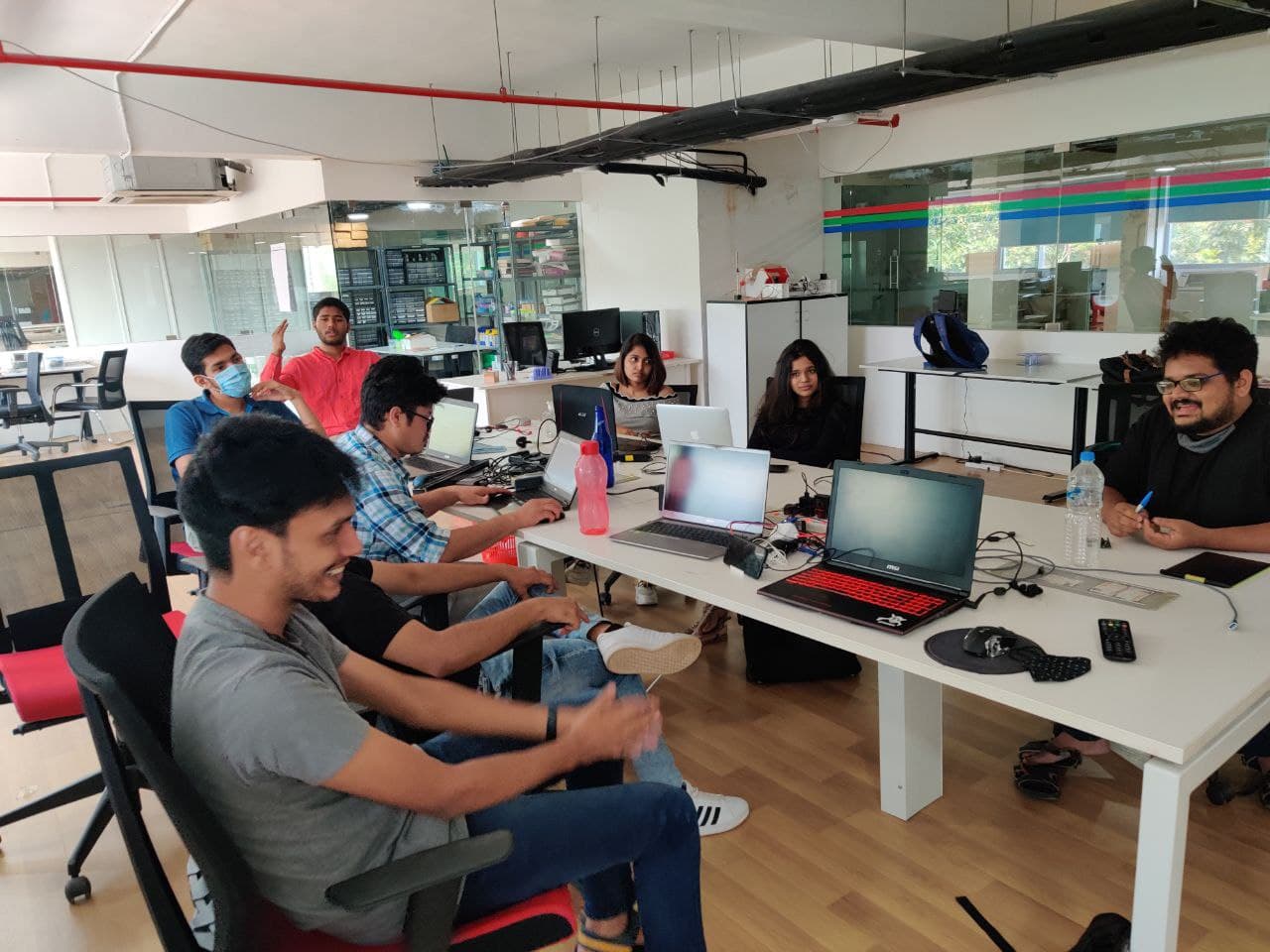
Further learnings from this week are listed below:
- Design a machine that includes mechanism + actuation + automation
- Document all the mistakes that we had made
- Document my individual contribution
- Build the mechanical parts and operate it manually
- Work as group with cooperation
- Have a lot of fun!
The following are the softwares that I have used for learning various operations:
- Autodesk Fusion 360 : Designing, Rendering & CAM
- Cura : Slicing
- Arduino IDE : Programming
The following tools were used thoughout the project:
- Ultimaker 2+
- Steel 6mm rod
- Servo Motor
- Electronic Power Installation Tool
- M3 Nut & Bolts
- Arduino & IDE
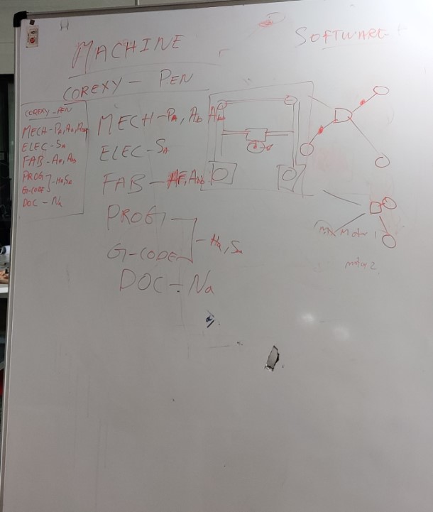
It was amazing to see our white board getting filled with new ambitious ideas without knowing that the reality was different. After a long brainstorming session we settled with Core X-Y Plotter with a dual acting end feed mechanism. Since I was good at mechanical design, I was given the task to design the end feed. I was also given the task to help my friend Neveena in documentation of the group page. The tasks were split among each member and I will add a photo of our messed up looking white board here:
| |
|
|---|---|
| Wednesday | Prof. Neil's class on Mechanical Design, Machine Design |
| Thursday | Brainstorming about various machines, selecting the mechanism, Splitting the tasks |
| Friday | Designing the parts |
| Saturday | Design iteration and constructive criticizm |
| Sunday | Refining the part |
| Monday | Test print of the mechanism & Fixing the tolerances and learning from mistakes |
| Tuesday | Helping with documentation and attachment of end feed to the frame of the machine |
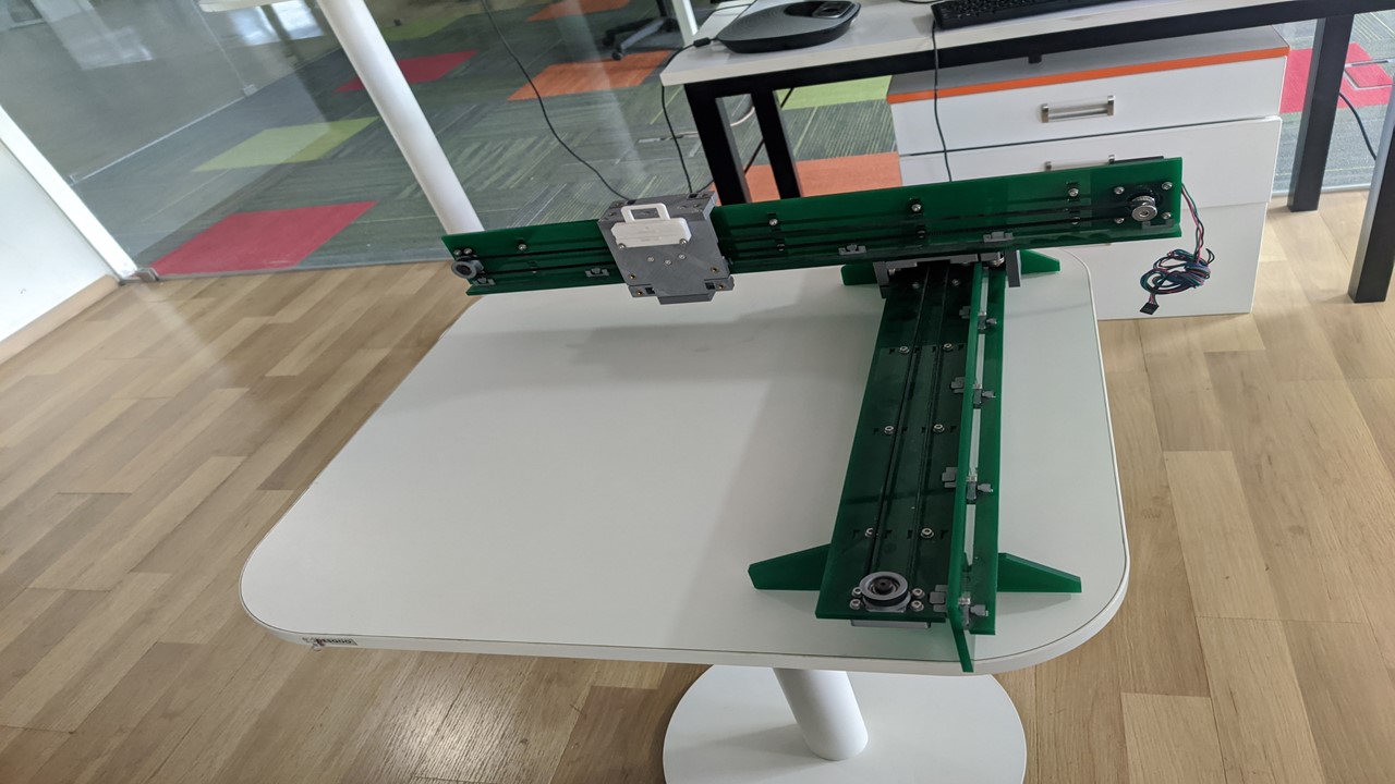
Since we are from Superfablab Kerala, we were introduced to the machine week based on work done by Pablo Nuñez, Epifanio Lorenzo, Yuichi Tamiya, Apeksha Bochare, Pradnya Shindekar during Bootcamp in our lab. The machine is a X-Y Plotter based on Platonic Gantry Design, it's linear motion is contrained with roller bearings, motion controlled by NEMA 17 stepper motor, laser cut acrylic frame with 3D printed parts. The machine had perfect clearances and accuracy so we tried to test the working of the machine at first and even though it took some time to get used to it but with help of our team members we made it to work. The machine inspired us to settled with tabletop based horizonal CNC machine based on Core XY Mechanism. The image of the machine is given below
Core XY is a cartesian motion platform which can be used for 2D plotting, we first came across this mechanism from Ilan Moyer's webpage. The mechanism is mainly used to move gantry where we can attach any end feed of choice. The main reason that we chose Core XY mechanism is due to the fact that it's dope, fast, simple and flexible compared to conventional mechanisms.
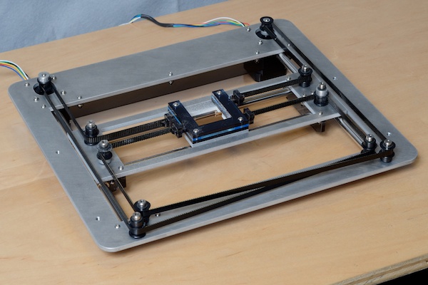
Mechanism
The figures given below gives an excellent explanation about the working of the Core XY Mechanism and I will explain further about it in next paragraph.
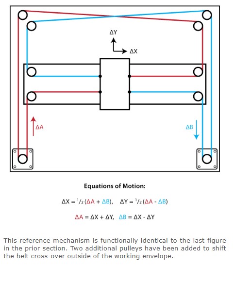
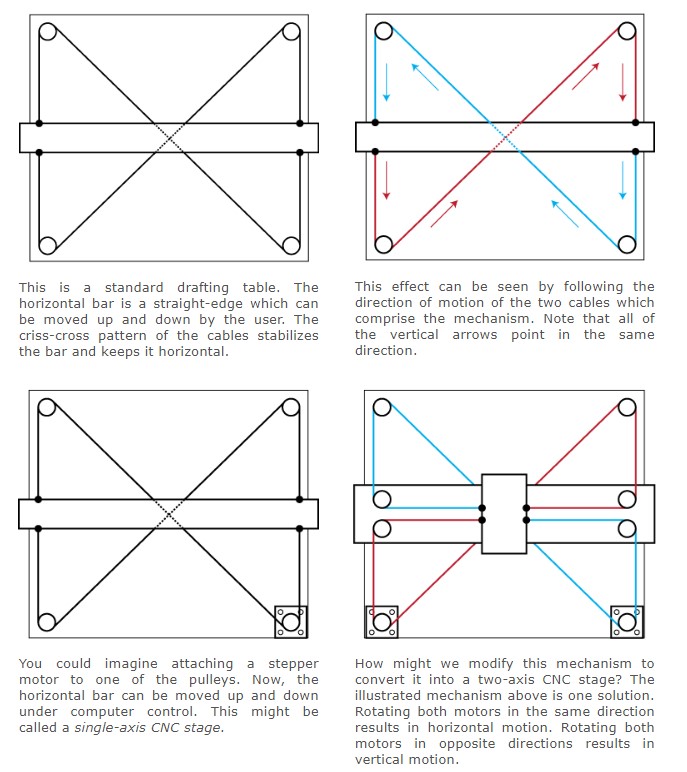
Here the motion of the pen will be:
- Horizontal when the motors rotate in the same direction.
- Vertical when the motors rotate in opposite directions.
- Diagonal if only one motor rotates.
Maths behind Core XY
If we rotate motor A counter-clockwise by an amount ∆A then the pen carriage will move horizontally to the right by an amount ∆X and vertically upwards by an amount ∆Y. The equation for this is:
∆A = ∆X + ∆Y --> 1If we rotate motor B counter-clockwise by an amount ∆B then the pen carriage will move horizontally to the right by an amount ∆X and vertically down by an amount ∆Y. The equation for this is:
∆B = ∆X - ∆Y --> 2The reason for the ∆Y sign/direction change is that the two timing-belts are moving in opposite directions... the timing-belt for motor A is being fed towards the pen which lets the pen to move upwards, whereas the timing-belt for motor B drags the pen downwards.
Horizonal Motion:
Rearranging equations (1) and (2) we get:
∆Y = ∆A - ∆X -->3
∆Y = -∆B + ∆X --> 4
Equating equations (3) and (4) we get:
∆A - ∆X = -∆B + ∆X --> 5
From which:
∆X = (∆A + ∆B)/2 -->6
Translating: the pen moves horizontally when both motors rotate in the same direction
Vertical motion:
Rearranging equations (1) and (2) we get:
∆X = ∆A + ∆Y --> 7
∆X = ∆B - ∆Y -->8
Equating equations (7) and (8) we get:
∆A + ∆Y = ∆B - ∆Y --> 9
From which:
∆Y = (∆A - ∆B)/2 --> 10Translating: the pen moves vertically when the motors to rotate in opposite directions and Collectively equations (6) and (10) infer diagonal movement if only one motor rotates.
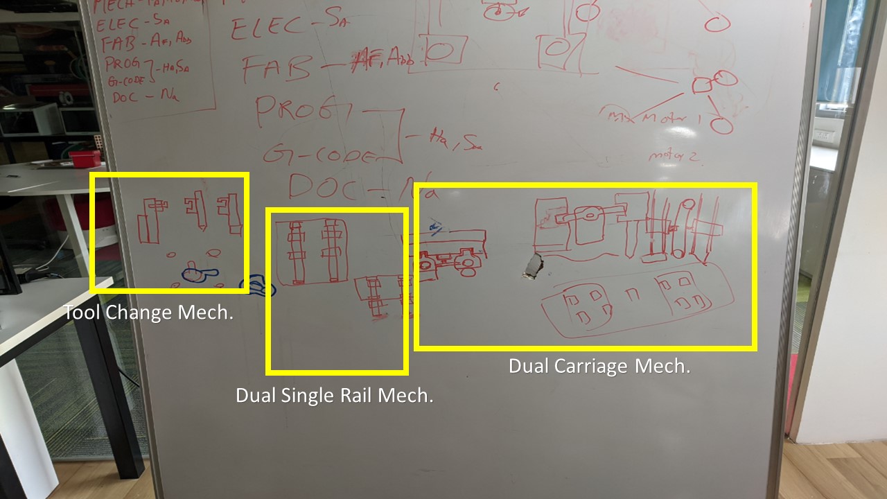
So my task for this week is to design an end feed mechanism to hold multiple pens/tools. Since I completed my major in Mechanical Engineering it was obvious that I should handle this interesting part. My friends Abel and Pallab were in charge of the basic frame and gantry mechanism while I had to complete the end feed mechanism. In layaman terms, the end feed mechanism in charge of moving the pen up/down depending upon the GCode from the microprocessor. To make it interesting, I thought of making a dual pen holding mechanism where one pen will touch the ground and other won't touch the ground when activated. The mechanism can easily be done with help of a single servo motor. To start with I had researched about various pen carriage mechanisms which included rail mechanism, magnetic type, spring loaded solenoid type etc. I along with my instructor Jogin had brainstormed about plethora of ideas which covered our small whiteboard and I will add it's picture right here.
Trial 1: Dual Rail - Single Pen Carriage Mechanism
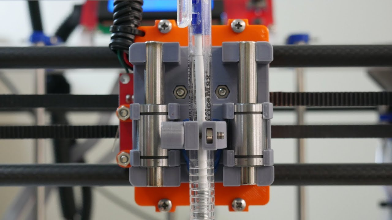
This is the most commonly used pen holding mechanism for generic CNC plotters. The mechanism is simple, there are 2 rails were a pen holder will be attached to. A servo arm attached to the base of the carriage pushes the pen holder thereby moving the pen up and down. The rails ensure that there are deflection to the motion of pen and springs ensure that proper reaction force is provided to the holder to keep it at the right position. The image given below shows a typical dual rail single pen carriage mechanism
So without further adeiu, I had tried to design similar mechanism. My only goal was to design and 3D print the mechanism so that I could understand it's motion, the mistakes that I had made and to learn from it. So I had used Fusion 360 to complete and 3D design and familiarized with various parts.
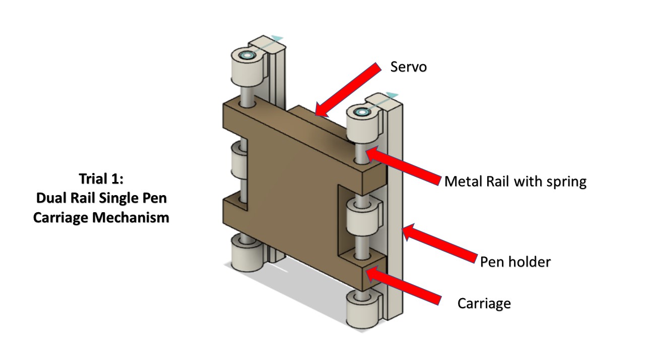
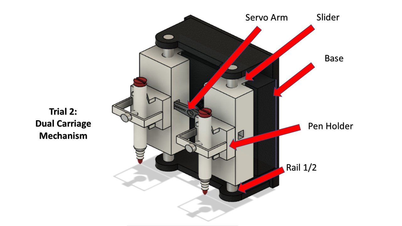
Here comes the irony, after I had designed the basic mechanism, I thought of trying out a new design which comprises of 2 pen holders sliding on individual rails controlled by a single servo. The idea was actually put forward by my instructor so I thought why not I could try out this one. In the mean time, I had volunatarily removed the multi tool changing mechanism as I found it to be complex to be completed within a span of 1 week. So here comes the Trial 2: Dual Carriage Mechanism.
Trial 2: Dual Carriage Mechanism
As suggested by my instructor, I tried to design a dual carriage mechanism which hosts 2 pen holders fixed in independent rails. In addition each holder is allowed to freely slide along a gap which restricts the any rotational motion of the slider. A single servo is responsible for the actuation of both pen holders during which one pen holder will be touching the ground plane while other holder won't be. Additional springs maybe provided for better actuation. Since this mechanism is kinda novel my first goal was to design a basic model of the mechanism and print it so that I could learn from my mistakes to make the final model perfect. My fablab had given me the permission to test out new designs by 3D printing it rather than testing it virtually. Similar to the previous one I had designed the dual carriage mechanism in Fusion 360 and the image will be provided below.
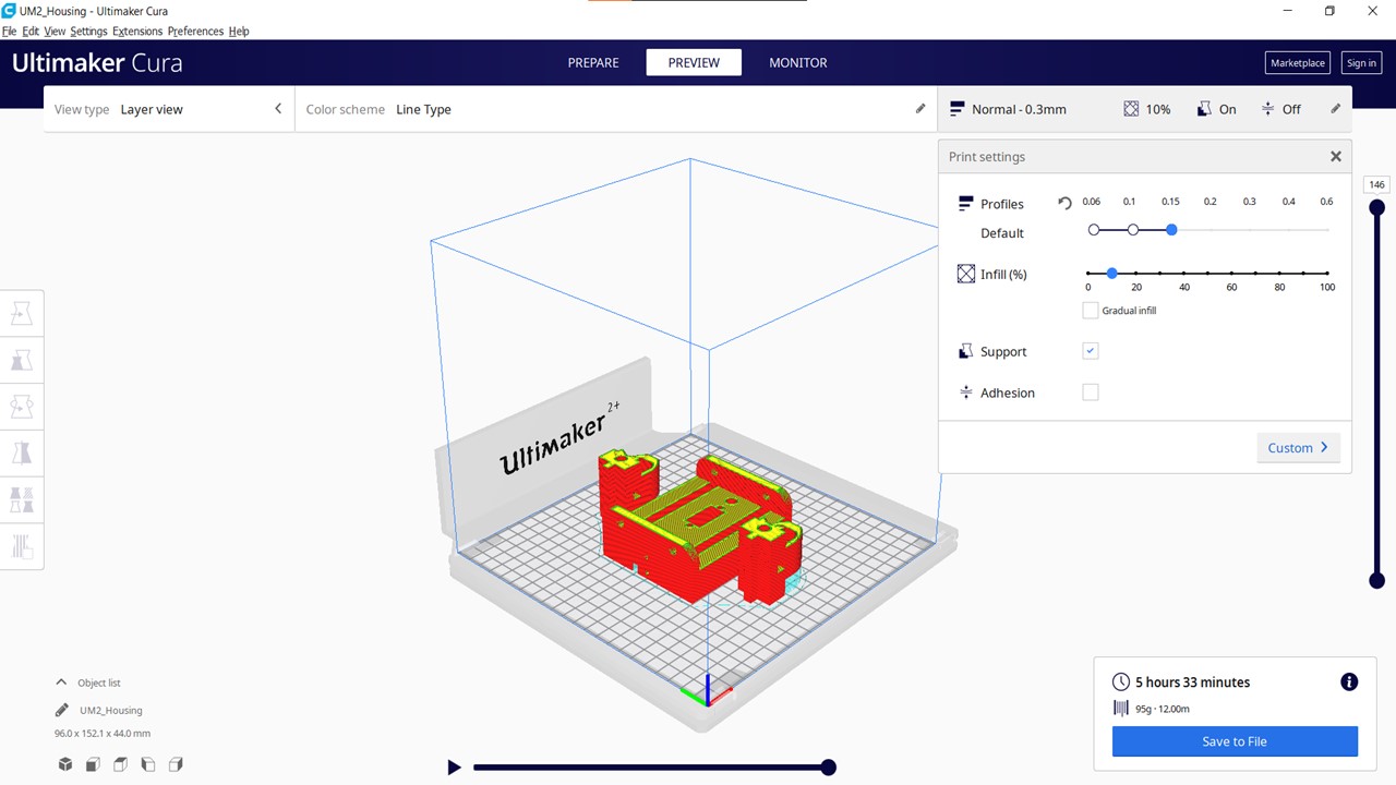
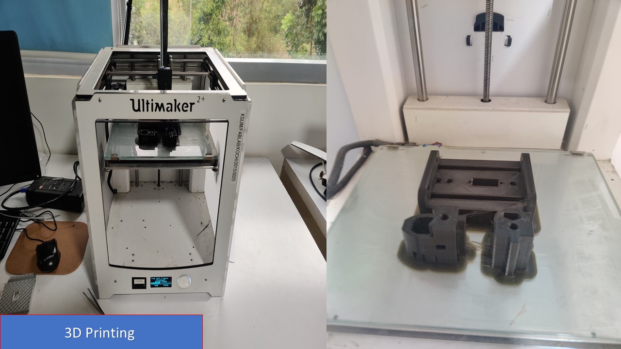
After completing the model, I had exported the bodies as STL files and had sliced using Cura to 3D print the second trial prototype. Since this is a trial print and inorder to reduce material wastage, I had provided only 10% infill with 0.8 wall thickness, layer height of 0.3mm and grid pattern. Since the sliders were oriented vertically, I had provided supports for the same The whole print was expected to be finished in 5.5 hrs but in reality it took a lot of time. The main motive of the print was to test the mechanism so I didn't print the pen holders at first inorder to reduce the material.
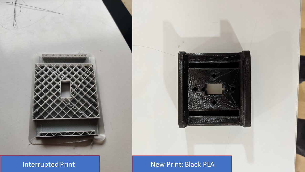
During the middle of the print, the material was over and the print stopped. I knew the material was about to end before the start of the print but I expected it to last. I think Ultimaker 2+ should have a feature to alert the quantity of the material remaining so that unncessary wastage can be reduced. The interrupted print is shown below as an evidence of mistake that I had made and the lack of feature of the machine to check the remaining material. To continue, I had replaced the material with a new roll so the print was succesfully completed.
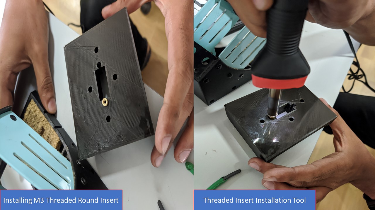
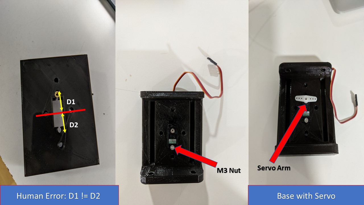
Next step was to install the M3 Threaded Round Insert to the holes for holding the servo motor. Here comes my first mistake, during designing I had gave different values for the position of M3 Screw holes from the center of servo. The mistake was made due to fact that the servo motor shaft is not exactly placed in the middle of the servo motor, but it was placed towards the top of the motor. Anyway, since the dimensions of the slot for the servo motor was perfect, I could easily fix the servo motor with 1 M3 Nut. Later I attached the servo arm and end feed mechanism is 50% completed. The next step is to cut the rod and add the rails to the base.
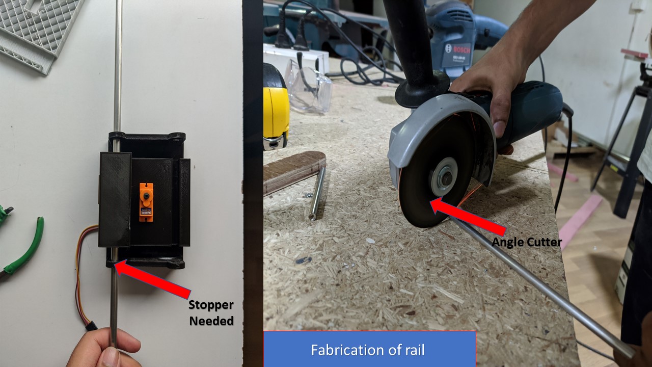
The next step is to fabricate the individual rails, for this I had savaged a 6.36mm dia steel rod from the lab and had reduced the length to the required amount using an angle cutter. My friend Saheen taught me about the safety aspects while using the cutting machine. Once the rods were cut, they were inserted to the respective slots by press fitting. Due to shrinkage, we had to widen the hole using a drilling machine (6.5mm bit). The process went out to be successful but due to my mistake, I forgot to add a stopper to one side of the slot so that the rail can be constrained.
Finally, with the help of my friend Saheen we had succesfully tested the mechanism and learned to lot of lessons from the first prototype. The lessons were:
- Always check the distance from the center of servo shaft to the pen holder/slider otherwise the sliding motion will be failure
- Don't forget to provide end stops for the rails and provide a bigger diameter for the shaft right from the design to compensate with the shrinkage
- Ensure that the position of the servo is optimum so that there will be ateast 1mm clearance for actuation of the slider
- Finally, run through the design several times and get feedback from others before printing the model.
- Please provide fillets, otherwise the 10% infill prototype will break like a milk biscuit when applied with a small pressure
Based on the lessons learnt from Trial 2, I decided to design the final prototype of the end feed. Due to our commitment to finish the prototype of the machine within 1 week, we even worked in weekends which helped me to refine my idea based on constructive criticizm from various team members. It had also given rise to collabrative design ideas from the team building the basic frame and me who is building the end feed.
Trial 3 (Final): Dual Pen Carriage Mechanism
I had made the following changes to the final design to accomodate the lessons I had learnt from previous prototypes:
- Provided fillets to the corners to prevent failure of the base
- Provided clearance to the holes which host the rails so that the drilling process post print can be prevented
- Verfied the position of the servo shaft and arranged the slot present in pen holder/slider to prevent the shaft from suprassing the limits
- Provided clearance for the sliding motion of pen holder for sufficient actuation during the motion
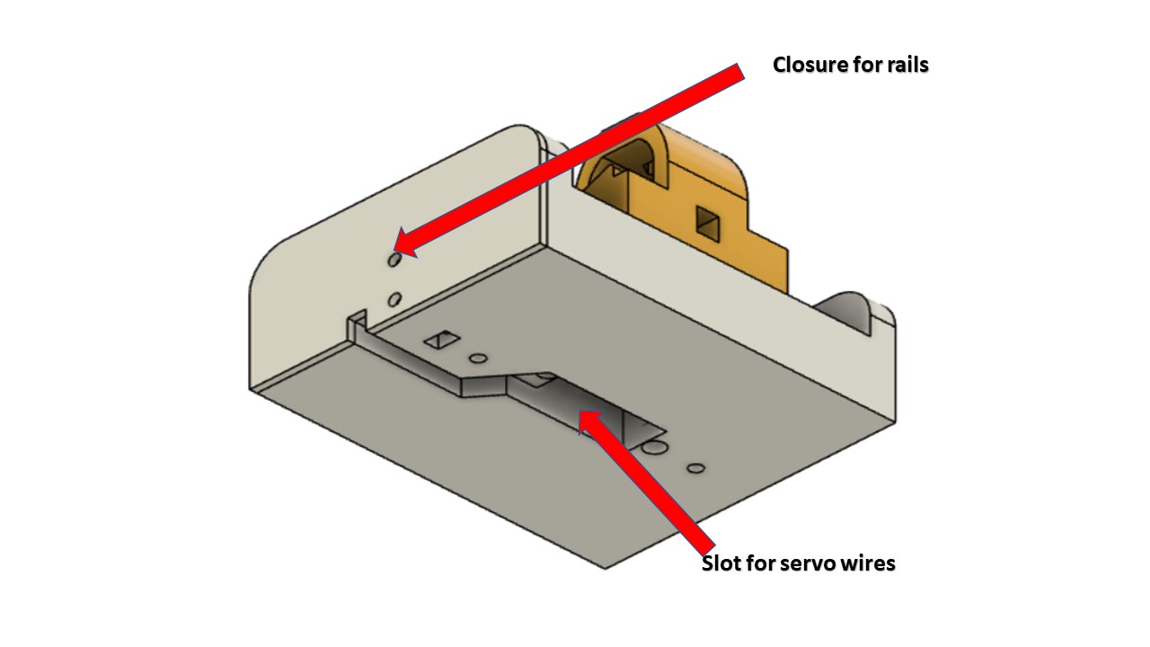
- Added end stop to one end of hole housing the rail and provided provision for removable closure at other end which can be attached by M3 Nuts
- Modified position of the servo mount holes so that (D1=D2) the servo motor can be mounted without any play
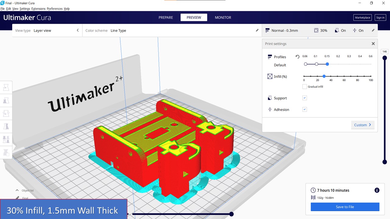
- For final prototype, I added 30% infill with support (printed keeping the model vertically) and increased wall thickness to 1.5mm
- Made a simple pen holder which can host upto 17mm dia pen and can be tightened using M3*30mm nuts with threaded insert
- Decreased the gap between 2 rails according the dimension of the servo arm
- Provided a path for servo wires by adding a pocket to the rear side of the model
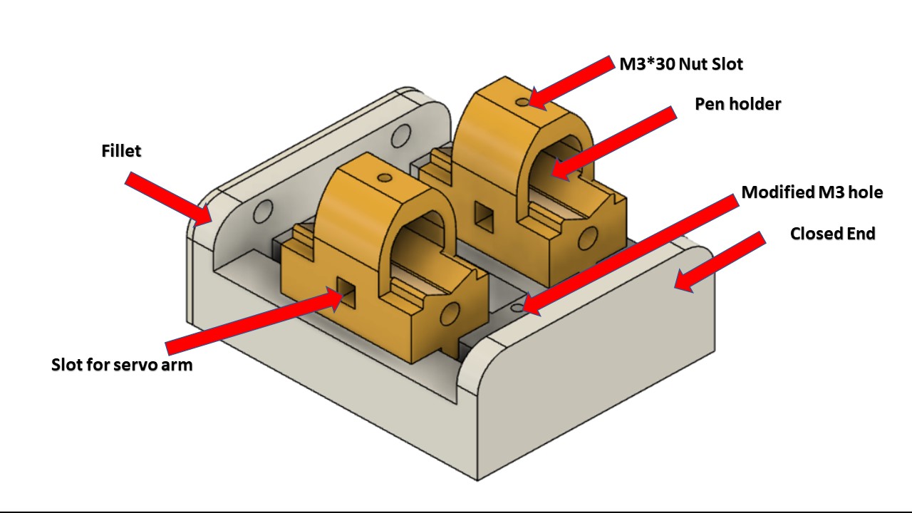
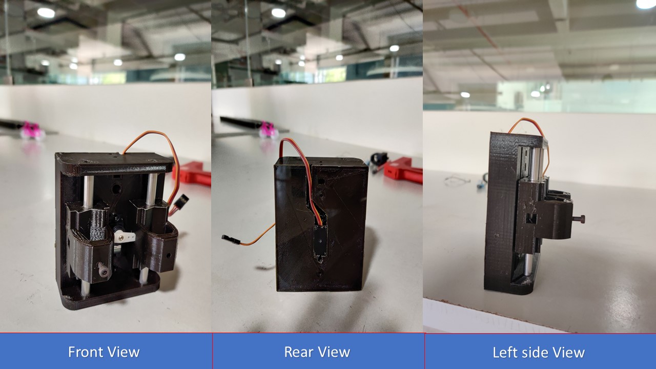
Hurray, this is the assembled end feed mechanism of our Core XY Plotter
Here comes the most interesting part of the whole process, since I had completed the end feed mechanism its now time to attach it to the gantry mechanism. In the mean time I had seen my friends assembling the rest of the mechansim.
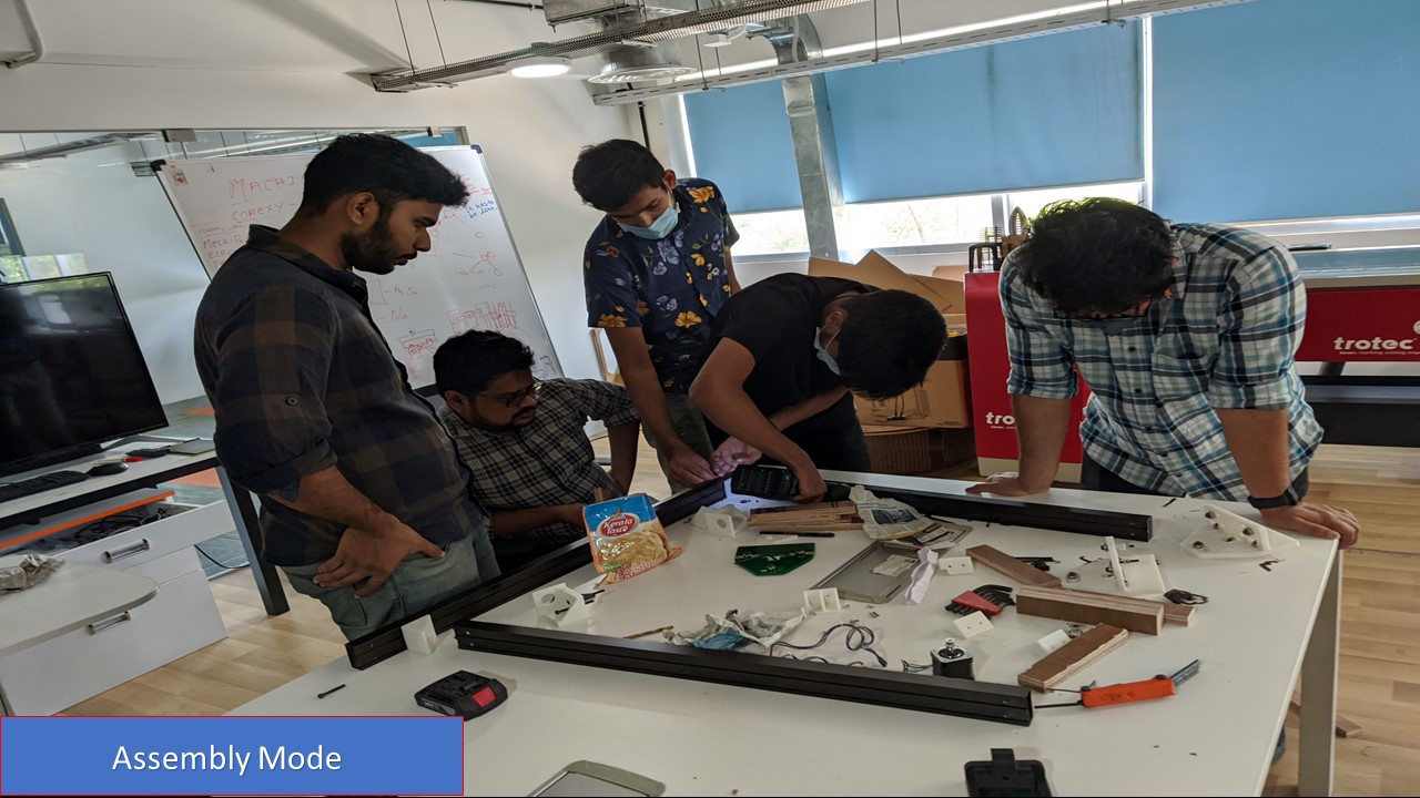
Since we didn't have enough time left and I had to leave early for the break, my friends attached the end feed mechanism that I had made to the gantry mechanism. My friend Pallab took a lot of effort to modify the gantry mechanism to fit my end feed (like aligning the M3 Holes) and finally it was attached as expected. The below video shows the testing of end feed mechanism without servo actuation. Since the servo for end feed had to be tested by my friend Saheen, we have manually placed the pen in the holder and checked the working of the whole mechanism.
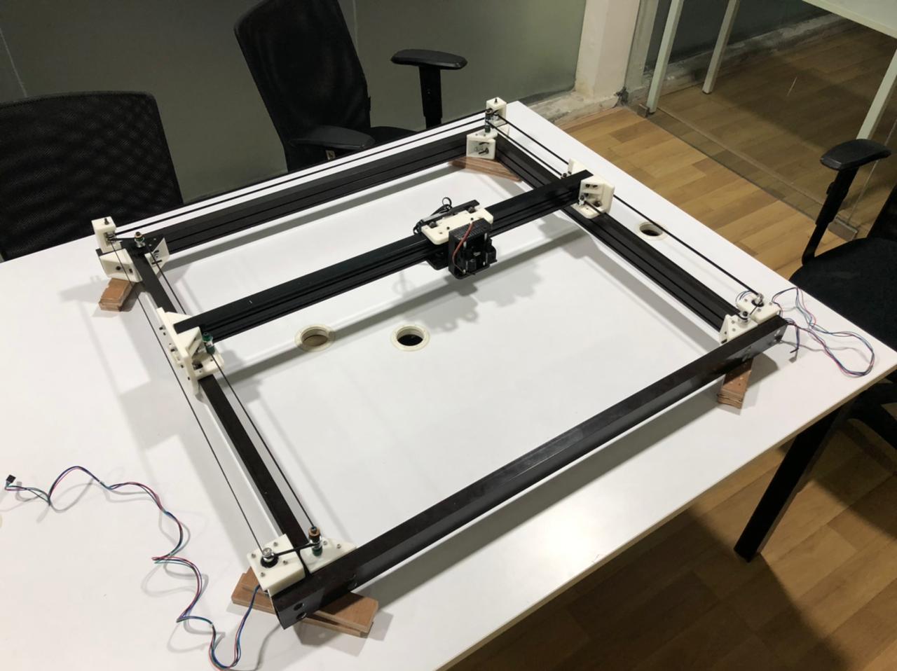
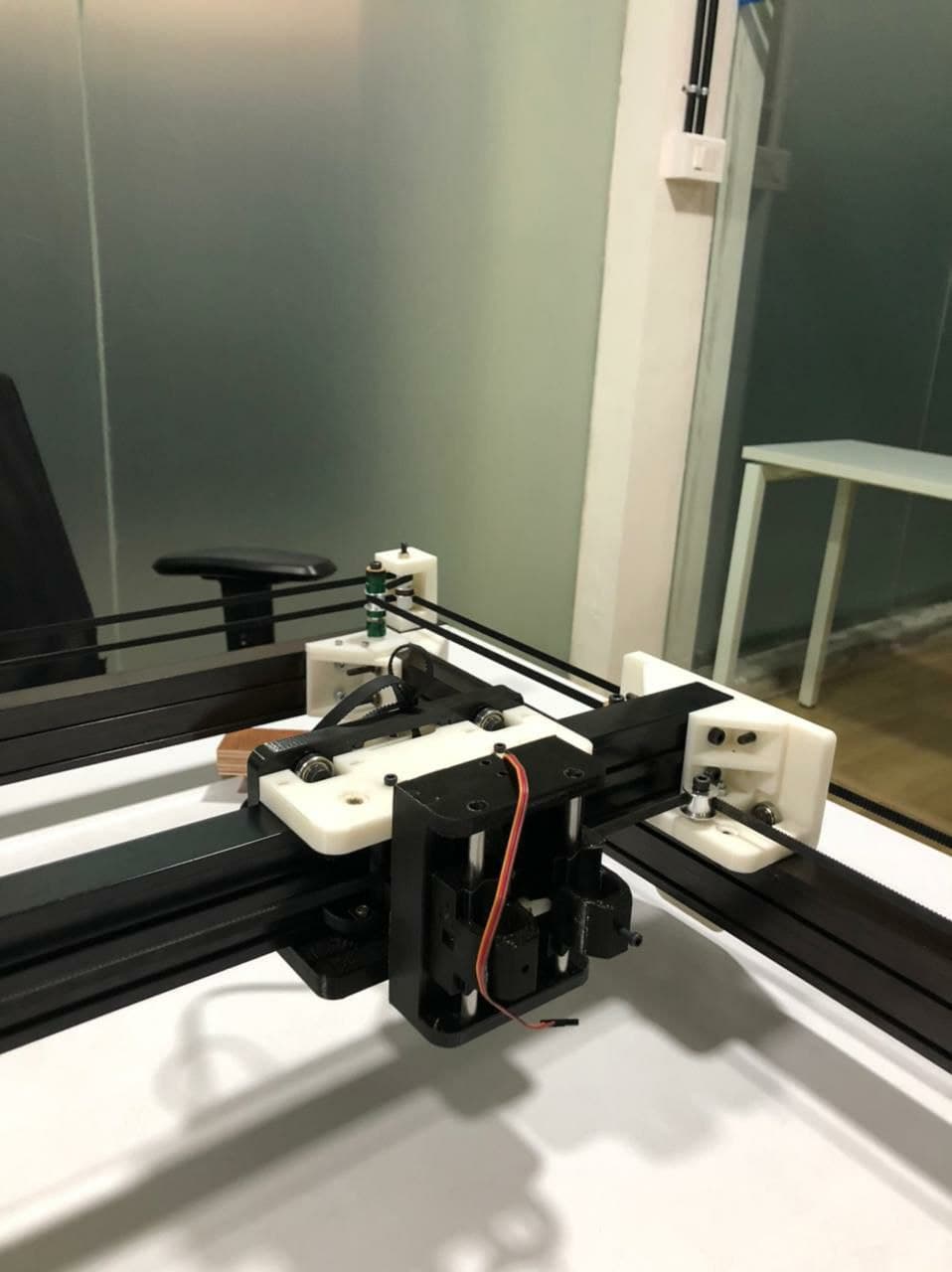
To be honest, I took a lot of effort to make this possible. A huge shout-out to all my friends Saheen, Pallab, Abel, Jai, Neveeena, Alfia, and Anandu and my instructors Jogin, Rahul and Yadu who helped me in every step of this design. That's all.